Meniscus tissue engineering has a structure problem.
It is not enough to make a construct that looks roughly like a meniscus, or one that produces the right general extracellular matrix. The native meniscus gets much of its function from the way collagen is organized through the tissue. Circumferential collagen fibres help the meniscus distribute load through the knee, while radial tie fibres help stabilize that network.
That type of organization is difficult to recreate in the lab.
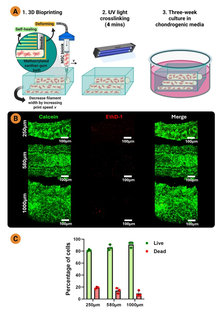
A recent study from Trinity College Dublin approached this problem using embedded cell-only bioprinting. The team printed mesenchymal stem/stromal cells into a methacrylated xanthan gum support bath, using the bath as a temporary physical boundary to guide tissue formation. After maturation, they used the CellScale BioTester to measure the mechanical response of bioprinted fibrocartilage sheets under hydrated tensile loading.
The work sits at the intersection of Cartilage and Meniscus Mechanics, 3D Bioprinting and Bioink Materials Testing, and the broader question of how physical boundaries can influence matrix organization in engineered tissues.
Using Embedded Cell-Only Bioprinting to Shape Fibrocartilage
The study began with a fairly direct question: could external geometric confinement guide collagen alignment in mesenchymal stem cell (MSC)-generated fibrocartilage?
Before moving into bioprinting, the researchers cast MSC-laden oxidized alginate into non-adhesive agarose channels. Over culture, the alginate degraded and the cells self-organized into tissue within the channels. The collagen that formed tended to align along the long axis of the boundary.
That early result gave them a reason to move into a more scalable biofabrication approach. Instead of relying on cast channels, the team used embedded cell-only bioprinting in an XGMA support bath. The bath helped hold the printed cell-only filaments in place during culture, while also acting as a physical boundary around the developing tissue.
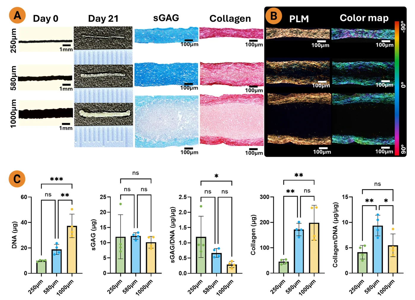
One useful part of the setup is that filament width could be changed by adjusting print speed. The authors compared 250, 580, and 1000 µm wide filaments, then looked at cell viability, matrix deposition, and collagen alignment.
All three widths supported viable cells. But the tissue organization was not the same.
Narrower Filaments Produced More Continuous Collagen Alignment
After three weeks in chondrogenic media, the bioprinted MSCs had formed handleable filaments that could be removed from the methacrylated xanthan gum (XGMA) bath. Histology showed sulfated glycosaminoglycan and collagen deposition, so the cells were producing a fibrocartilaginous matrix.
The more interesting difference appeared in the polarized light microscopy images.
In all groups, collagen tended to align along the long axis of the filament. But the 250 µm filaments showed the most consistent alignment through the tissue depth. In the thicker filaments, alignment was stronger near the edges and less organized toward the core. That suggests the boundary effect may only reach so far into the developing tissue.
For meniscus tissue engineering, this is a practical observation. A printed construct may have the right outer shape, but the spacing and geometry of the printed features can still influence what happens inside the tissue during culture.
The authors selected the 250 µm width for later experiments because it gave more homogeneous collagen alignment.
This also connects nicely with another CellScale research highlight on cell-only bioprinting of articular cartilage, where printed cell populations and support bath design were also used to influence tissue architecture. The meniscus study pushes that idea toward fibrocartilage and circumferential matrix organization.
Testing Whether Cell Mechanotransduction Was Driving the Alignment
The team then looked at whether this boundary-guided collagen alignment depended on cell-mediated contractility and mechanotransduction.
They inhibited YAP and ROCK pathways during culture. These pathways are often involved in how cells sense and respond to their physical environment, including cytoskeletal organization, nuclear shape, and force generation. In the study, inhibition disrupted cell and nuclear alignment. The cells no longer showed the same organized cytoskeletal structure seen in the control filaments.
But collagen alignment remained.
That is the part that makes this meniscus tissue engineering paper especially interesting. The matrix still followed the long axis of the physical boundary, even when cell and nuclear alignment were disrupted. The authors are careful not to overstate this, since they only tested two mechanotransduction pathways. Other pathways could still be involved. But it appears that geometric confinement itself was a major cue for collagen organization.
For readers interested in the cell response side of the work, this is where the study overlaps with Mechanotransduction and stem-cell-driven tissue remodeling. It is not simply a printing paper. It is also asking how much of the final tissue structure comes from the cells actively organizing their environment, and how much comes from the physical boundaries imposed during culture.
Scaling the Approach into Fibrocartilage Sheets
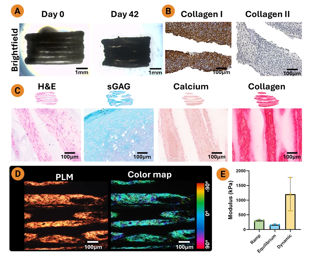
Once the filament work showed that narrow printed features could guide collagen alignment, the authors scaled the approach into larger sheet-like constructs. They printed adjacent 250 µm MSC filaments into the XGMA bath and cultured them to form anisotropic fibrocartilage sheets.
By day 42, the constructs showed positive sGAG and collagen staining. Immunohistochemistry showed strong collagen I staining and weaker collagen II staining, consistent with a fibrocartilage-like phenotype. Polarized light microscopy again showed collagen alignment along the printed direction.
This is where mechanical testing entered the meniscus tissue engineering study.
How the BioTester Was Used in the Study
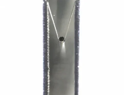
The researchers used a tensile biaxial tester (our BioTester) with a 23 N load cell to test the 3D bioprinted fibrocartilage sheets. The testing was performed at 37°C in a PBS bath, which helped maintain hydrated, temperature-controlled conditions during mechanical characterization.
The protocol included a small preload, then a 10% strain hold for 10 minutes to allow the construct to approach equilibrium. After that, the samples were dynamically tested for five cycles at 1 Hz.
From these measurements, the authors calculated:
- Ramp modulus
- Equilibrium modulus
- Dynamic modulus
The reported dynamic modulus was higher than the ramp and equilibrium moduli. That makes sense for hydrated fibrocartilaginous tissues, where fluid pressurization during cyclic loading can affect the apparent mechanical response.
This mechanical testing part of the meniscus tissue engineering study connects directly with Tensile Testing, Hydrated and Temperature Controlled Testing, Stress Relaxation Testing, and Viscoelastic and Time-Dependent Testing. The construct was not just pulled until a number came out. The authors used a multi-step protocol to capture immediate, equilibrium, and dynamic behaviour.
For meniscus tissue engineering, that distinction matters. The native meniscus is a hydrated, load-bearing fibrocartilage. Its function depends not only on collagen content, but on how the solid matrix and interstitial fluid respond during loading.
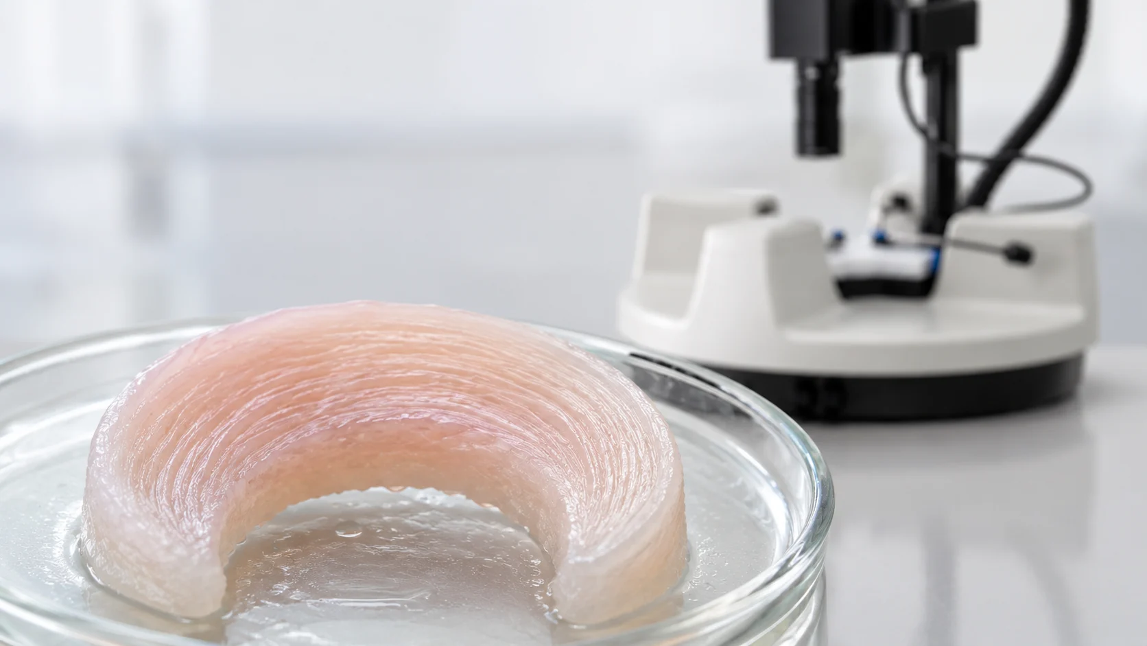
Printing a Meniscus-Like Construct with Circumferential Collagen Organization
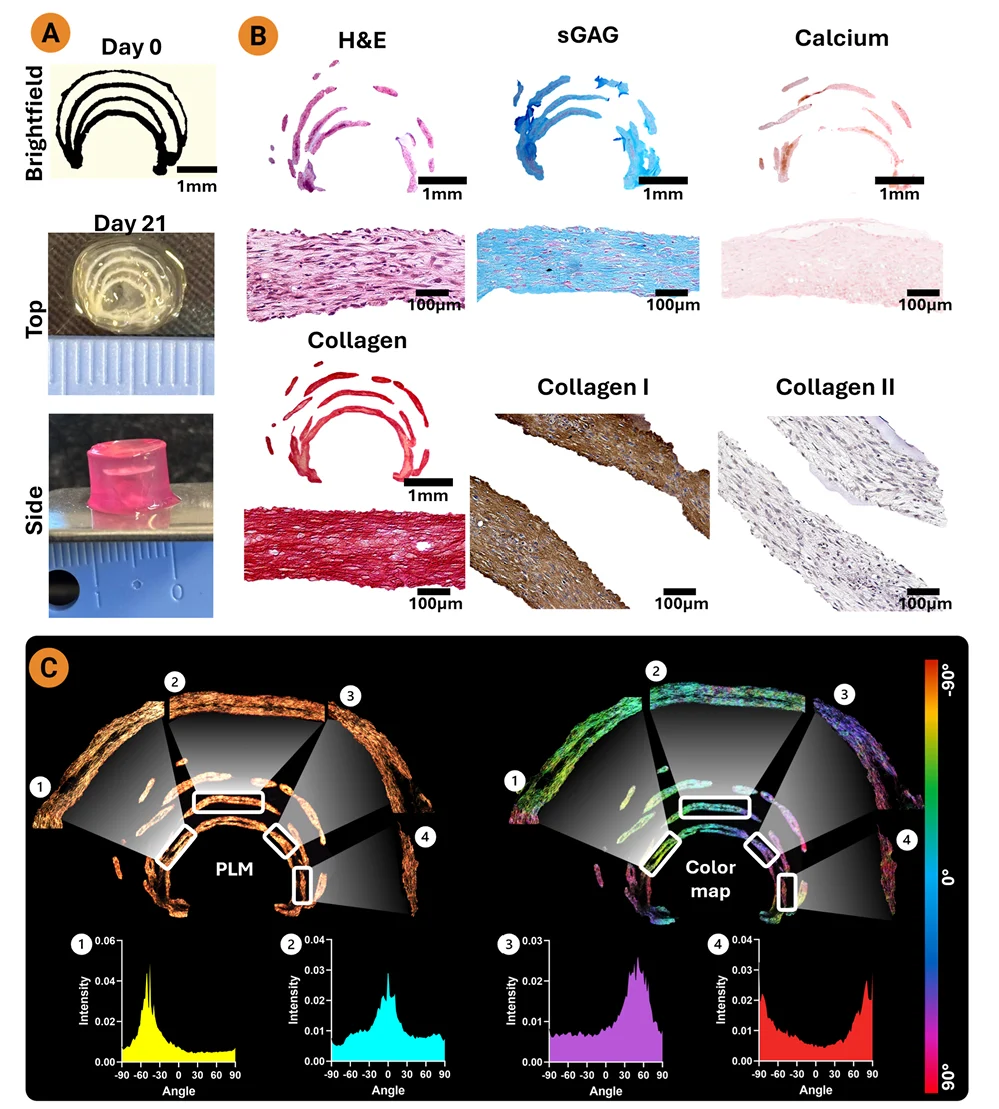
The final step was to move from straight filaments and rectangular sheets to a meniscus-like geometry.
The researchers printed concentric circumferential MSC lines into the XGMA support bath. After culture, the construct stained positive for sGAG and collagen, showed stronger collagen I than collagen II staining, and had little calcium deposition. Polarized light microscopy showed that collagen followed the printed path, producing a circumferential organization that resembled one of the key structural features of the native meniscus.
This is a strong visual endpoint for the study. It shows that the printed geometry was not only defining the gross construct shape. It also appeared to influence the internal collagen architecture that developed during culture.
The authors are clear that these constructs are not yet native meniscus replacements. The mechanical properties are still much lower than native tissue, and the study did not fully recreate the wedge shape or inner and outer regional variation of the meniscus. Nutrient diffusion may also become a concern as constructs become larger and more layered.
Still, the approach gives researchers another way to think about scaffold-free or temporarily supported meniscal graft fabrication. Instead of adding permanent fibres or reinforcing materials to impose structure, the physical environment around the cells can be used to guide how the tissue organizes as it matures.
That is a useful idea for meniscus tissue engineering, and it may extend to other aligned musculoskeletal tissues where collagen architecture is closely tied to function. Similar questions come up in tendon, ligament, cartilage, and other fibrocartilaginous tissues.
Why Mechanical Testing Matters in a Structure-Focused Study
Much of this meniscus tissue engineering paper is about alignment, staining, and tissue organization. But for meniscus tissue engineering, structure is only part of the story.
A construct can show organized collagen and still fall short mechanically. It can also behave differently under a fast cyclic load than it does during a slower ramp or a hold. That is why mechanical testing is a useful checkpoint in studies like this.
The BioTester measurements gave the authors a way to connect the engineered tissue structure to tensile and dynamic response. The dynamic modulus result was not treated as proof that the construct matched native meniscus. Instead, it gave a quantitative view of how the matured bioprinted sheet responded under hydrated cyclic loading.
That kind of measurement becomes especially useful when comparing different printing patterns, maturation timelines, biochemical cues, or support bath designs.
For related bioprinting work, CellScale has also covered GelMA bioink mechanics in 3D bioprinting, where mechanical characterization was used to understand how bioink formulation and printed structure influence construct behaviour.
Citation
Aliaa Sherif Karam, Gabriela S. Kronemberger, Kaoutar Chattahy, Diana Eveline Sanchez-Amador, Michael G. Monaghan, Daniel J. Kelly. Embedded cell-only bioprinting to engineer structurally aligned meniscal fibrocartilage. Materials Today Bio. Volume 39. 2026. 103308. ISSN 2590-0064. https://doi.org/10.1016/j.mtbio.2026.103308.
About the BioTester
The BioTester is CellScale’s dedicated biaxial testing machine for soft tissues, planar biomaterials, and engineered constructs. Researchers use it for equibiaxial and non-equibiaxial testing, strip-style tensile testing, hydrated testing, and imaging-based strain measurement.
In studies like this one, the BioTester can be used when engineered tissues need to be tested in fluid and at controlled temperature, rather than in dry bench conditions. That is especially relevant for soft tissues and tissue-engineered constructs where hydration, handling, and time-dependent behaviour can affect the measured response.
For meniscus tissue engineering, the instrument provides a way to measure how developing fibrocartilage constructs respond to controlled tensile and cyclic loading. In this study, that meant testing bioprinted sheets in a 37°C PBS bath and calculating ramp, equilibrium, and dynamic moduli from the resulting force and strain response.